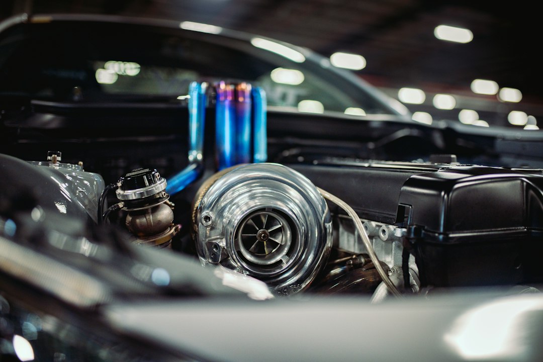

Street use and track use place different demands on the system. A commuter usually benefits from quick response, predictable part throttle, and smooth transitions rather than a turbo sized only for a peak dyno figure. A track car may hold high load for longer periods, making turbine restriction, intake temperature, and stable boost control more important. Review the engine’s airflow needs across its usable rpm range, not just at redline. A large turbo can be capable of the desired output while feeling sluggish in normal driving. A smaller unit may respond well but run out of airflow before the engine reaches its intended power level.
A compressor map helps put those compromises on paper. It relates pressure ratio to airflow and shows the area where the compressor is expected to operate efficiently. Pressure ratio is based on compressor outlet pressure compared with inlet pressure, so a boost gauge reading alone does not describe the full workload. Low airflow at a high pressure ratio can move the operating point toward surge, where flow becomes unstable and may reverse repeatedly. Before reviewing a Garrett G Series II application, gather engine airflow estimates, rpm targets, and intake conditions. Research on Turbosmart hardware should support that matching work rather than replace it.
The turbine side introduces a separate set of choices. A turbine housing’s A/R ratio describes inlet area in relation to the housing radius. A smaller ratio can favor earlier response, while a larger ratio may reduce restriction at high flow, although housing design and engine behavior determine the actual result. Exhaust manifold volume, cam timing, displacement, and intended rpm range belong in the same discussion. Choosing a housing solely for maximum top end can leave the wastegate working excessively hard to recover response. Gate size and placement also matter. The valve must bypass enough exhaust flow to control turbine speed once the target boost level is reached.
Boost control depends on hardware, plumbing, and calibration working together. A wastegate regulates exhaust flow around the turbine, while a pressure or electronic control system manages how and when it opens. Spring pressure should suit the intended operating range, and the reference line should be short, secure, and protected from heat. A workshop habit that prevents rework is to label every hose before installation and photograph the routing before the car leaves the lift. Incorrect ports, soft lines, or a poorly chosen reference source can cause creep, spikes, or oscillation that may be mistaken for a tuning problem.
Supporting components also influence the result. An intercooler lowers compressed air temperature, but its core and pipework introduce volume and pressure drop that the calibration must accommodate. A blow off or bypass valve gives displaced air a controlled path when the throttle closes, reducing the chance of compressor instability during a shift. Check oil feed restriction, drain angle, crankcase ventilation, vacuum connections, and exhaust joints before making power pulls. A technician should also move the wastegate actuator through its range, inspect the seat for interference, and confirm that boost, air fuel ratio, and intake temperature sensors show plausible readings. A controller cannot correct a leaking hose or poorly supported oil drain.
A sound installation process is methodical. Confirm the use case and engine data, estimate airflow, select the turbo and turbine housing, then size the wastegate and valve around that selection. During calibration, raise load gradually while recording boost, air fuel ratio, intake temperature, and exhaust backpressure when the equipment allows it. A second practical habit is to compare the current tune with the build sheet after every hardware change, since a forgotten spring setting or revised injector data can distort the diagnosis. For additional turbocharger selection guidance, use the system’s observed behavior to decide whether the fault lies in sizing, plumbing, heat management, or calibration before replacing parts.